
There is no single hole-to-bend clearance valid for every material, tool and feature. Define whether the distance runs from a flat-pattern bend line, a finished face or a bend tangent, and whether it ends at the hole center or edge. Then review the geometry, actual tooling and finished feature requirements together.
A hole that accepts a loose fastener may still fail a close-fitting pin requirement. A thread or countersink may lose its function even when the flange looks satisfactory. Put dimensional and functional acceptance criteria on the drawing before releasing the process.
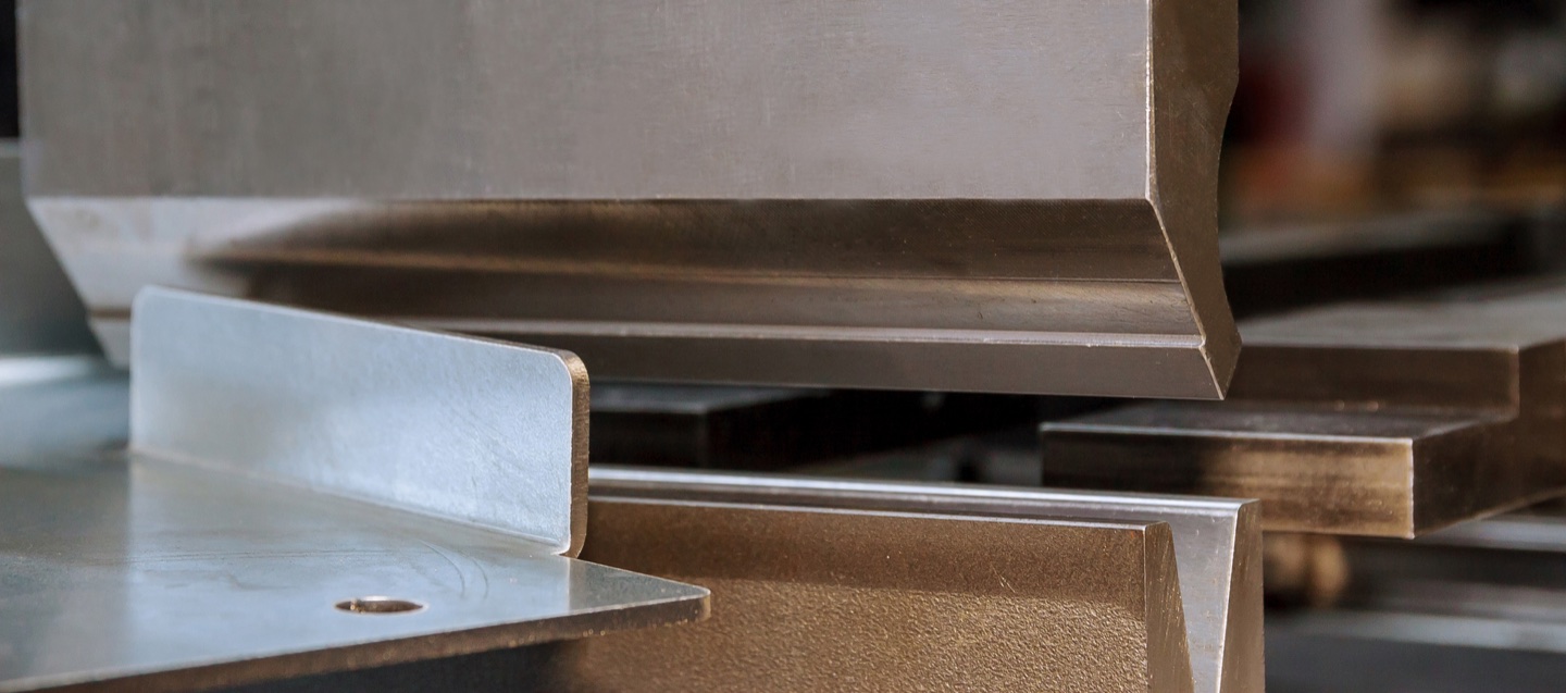
Why holes and slots can distort
Material around the bend changes shape during forming; a nearby opening can change with it. WILA identifies holes, slots and cut-outs close to the bend line as deformation risks and describes tooling options to reduce distortion. This supports an application review, not a universal clearance or a Rucheng capability guarantee.
Technical references: WILA / SendCutSend.
Define the distance before checking the drawing
Keep flat-pattern checks separate from finished-part acceptance. Record material grade, measured thickness, target angle and radius, forming method and tool identifiers. A thickness-only rule leaves several of these variables unspecified.
| Drawing reference | What to confirm |
|---|---|
| Hole center to flat-pattern bend line | Identify the bend-centerline mark and hole center on the same drawing revision. |
| Hole edge to flat-pattern bend line | Use the nearest edge. For a slot, assess its orientation and full outline. |
| Hole center to finished flange face | Specify the finished face and datum system. Do not substitute a flat distance. |
| Hole edge to bend tangent | Define inside or outside tangent, the surface and how the distance will be measured. |
| Countersink, thread or inserted hardware | Review the complete feature, not only the pilot hole, and its operation sequence. |
Worked example: center distance is not edge distance
Hypothetical flat pattern: a circular hole is 6 mm in diameter and its center is 12 mm perpendicular to a straight bend-centerline mark. The nearest edge is 9 mm from that mark. Comparing 12 mm with an edge-distance requirement overstates the available distance by 3 mm.
Edge distance = center distance - hole diameter / 2 = 12 - 6 / 2 = 9 mm.
This is geometry on one flat drawing, not a minimum-distance recommendation. It does not predict distortion or approve 9 mm for production. For a noncircular cut-out, locate the nearest point on the actual outline. A finished tangent or flange-face dimension needs its own reference.
Supplier rules retain their original scope. SendCutSend describes a half-die-width check from the flat bend line for its tapped and countersunk features, processed before bending. Its hardware rules use other reference information. These are that provider's process requirements, not universal press brake specifications.
Compare design and process options
Review these alternatives with the designer and machine/tooling supplier. A different die opening or forming method also changes other constraints; it is not a complete process approval.
| Option | Required review |
|---|---|
| Move the feature or revise the flange | Check assembly interfaces, fastener access and approval of the drawing revision. |
| Review alternative tooling or forming | Confirm compatibility, load limits, support, clearances and representative trials. WILA describes special tooling and bottom-bending options; availability is configuration-specific. |
| Create or finish the feature after bending | Check access, workholding, finished datums, achievable tolerance and secondary-operation cost. |
| Revise the feature requirement | Obtain design approval and define a functional acceptance method for any permitted distortion. |
Extra back gauge axes help positioning where the part permits it; they do not by themselves prevent hole distortion. Review positioning, forming and tool capacity separately.
First-piece inspection record
Agree on measurement methods and acceptance limits before a trial. Qualified personnel must follow the actual machine and tooling procedures. This checklist records results; it is not an operating instruction.
- Drawing and material: revision, grade, actual thickness and required orientation; feature ID, dimensions, tolerances, datums and intended function.
- Process: approved sequence, machine/tool IDs, forming method, die opening and target angle/radius.
- Before and after forming: measure feature size and location against the correct reference; include slot width or roundness and flange dimensions where specified.
- Acceptance: record the drawing-required pin, gauge, fastener or assembly check, reviewer and decision. Retain original results and identify changes between trials; do not transfer approval to another material or setup without review.
Questions about holes near bends
Is twice the sheet thickness always enough between a hole and a bend?
No universal value is established here. Confirm the datum, feature boundary, material, tooling and finished requirements. A process-specific rule must retain that process's scope.
Does a six-axis back gauge prevent hole distortion?
Axis count describes controlled positioning functions, not hole deformation. Positioning, tooling suitability and the finished feature require separate checks.
Can I drill or finish the hole after bending?
It is an option when access, workholding and finished datums allow it. Review the sequence, achievable tolerance and cost before selecting it.
Prepare a press brake inquiry
Send material and thickness range, bending length, representative geometry, finished tolerances and batch mix. Mark bend/feature datums and any tapping, countersinking, hardware installation or post-bend operations. Request tooling and configuration review against those requirements, not only a tonnage or axis-count recommendation.
Send press brake quote requirements