
Press brake springback is the elastic recovery of a bent part after the forming load is removed. In air bending, compensation normally requires a controlled overbend that the actual tooling and material can accommodate. First separate the drawing angle, the angle under load and the released angle. A part that finishes 2° away from its target has a 2° final-angle error; that alone does not measure its springback. Qualify the setup, make representative trials and verify the released geometry before saving a correction.
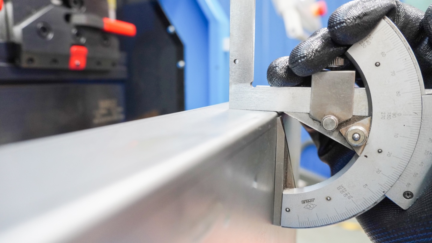
Which angle are you measuring?
This guide uses the interior included angle between the two flanges: a smaller number means a more closed bend. A controller or drawing may instead describe rotation from flat. Identify the convention before comparing numbers; at 90° the two conventions coincide, which can conceal a misunderstanding.
| Angle state | What to record |
|---|---|
| Target, θtarget | Required released geometry and drawing tolerance. Keep this separate from the machine command. |
| Under load, θloaded | Actual angle from machine-approved in-process sensing, with its location and measurement method. A programmed angle is not automatically this value. |
| After release, θfree | Measured unloaded angle at the agreed position and reference faces. Record support and inspection conditions. |
Do not insert a hand gauge between loaded tools or defeat a safeguard to obtain a reading. Where approved loaded-angle sensing is unavailable, use the released-part error to qualify the process and label actual springback as unmeasured.
One trial can have two different angle differences
Illustrative arithmetic only: suppose a validated sensor reports an 87.8° loaded included angle, inspection after release gives 92.1°, and the drawing calls for 90°. Using comparable locations and conventions:
Recovery: Δθ = θfree − θloaded = 92.1° − 87.8° = 4.3°. Final-angle error: e = θfree − θtarget = 92.1° − 90° = +2.1°.
The example does not recommend an 87.8° machine setting or a 4.3° correction. The control may already incorporate compensation. Inspect its field definitions and the approved setup before changing a value; then verify a new trial. Without the loaded measurement, only the +2.1° residual error is established.
Why a material name is not a compensation setting
SSAB identifies steel strength and die-width-to-thickness ratio as influences on springback and explains why the die must allow overbending. These are reasons to verify the particular grade and tool combination, not a universal degree allowance. Keep the specified bend radius and material bendability limits when considering another die or punch.
Technical reference: SSAB: Springback.
Changing a die to alter recovery also changes the forming setup. Review contact conditions and the complete load path. WILA notes that holders and the press brake can limit capacity even when the tool rating is sufficient. An angle result or a theoretical force estimate cannot approve a new forming process on its own.
Technical reference: WILA.
A trial record that can be reused
Save the conditions that make the result identifiable. A correction without its setup record is difficult to transfer reliably to another batch or machine.
| Record group | Capture with the trial | Reason to recheck |
|---|---|---|
| Material | Grade or alloy and temper, lot, measured thickness and rolling orientation. | Different stock or orientation; do not assume a nominal material name fixes recovery. |
| Tooling and part | Punch/die identifiers, V opening, radius, bend length and support arrangement. | Tool, length, station or support changed; review contact, clearance and load again. |
| Program | Machine, program revision, angle convention, correction field, unit and existing value. | Another control or correction mode; verify meaning and sign rather than copying a number. |
| Inspection | Gauge/method, reference faces, marked positions, loaded sensing if available and released readings. | Measurement setup changed or a discrepancy cannot be reproduced. |
| Acceptance | Drawing limits, angle and flange checks, first-piece result and approved repeat settings. | Any relevant material, program or setup change; use the job's agreed inspection plan. |
Validate a correction without hiding the cause
- Freeze the drawing revision and setup. Check actual stock, tooling data, clearance, support and the machine/tooling limits before the trial.
- Measure released geometry consistently. Mark left, center and right positions for a long bend; use the same reference faces and avoid confusing flange length with angle.
- Check whether the error is repeatable. Compare the same position across trial parts separately from different positions on one part. Do not average away a local defect.
- Follow the controller's documented correction method. Preserve the original program and record one authorized change at a time. Degrees and ram-depth millimeters are not interchangeable.
- Inspect another representative trial against the drawing. Save the final setup only after the required angle, dimensions and surface condition pass; establish repeat checks under the job's quality plan.
Separate a consistent offset from variation
For an illustrative 90° target, three comparable released readings of 92.0°, 92.1° and 92.2° have a mean of 92.1° and a range of 0.2°. The mean error is +2.1°, while the range describes this small sample's spread. Neither value is a process-capability result or an acceptance tolerance. A mean correction does not establish that future parts will meet the drawing.
If a single long part instead measures 92° at each end and 94° at its center, record the position pattern. SSAB distinguishes material recovery from machine deflection and explains the role of crowning. Investigate tool seating, support and machine compensation before applying a global offset. The three readings alone do not prove which factor caused the difference.
Technical reference: SSAB: Press bending.
What automatic angle feedback does and does not establish
TRUMPF describes ACB Laser and ACB Wireless as systems that sense angle and springback and control the press beam; it also notes that suitability depends on the application. This is an attributed example, not a claim that every CNC machine includes such equipment. For a proposed Rucheng configuration, confirm the actual sensor, control integration and accessible measuring surfaces, then demonstrate the required result on a representative part. Continue the agreed inspection of flange dimensions and complete geometry.
Technical reference: TRUMPF.
Technical reference: TRUMPF (PDF).
Springback questions
Can I use one overbend allowance for every sheet of the same thickness?
No. Identify the material and setup, then verify the released result. A retained correction is a record of a qualified combination, not a material constant or a guarantee for another lot.
Will changing K-factor fix a springback angle error?
K-factor is used in flat-pattern bend-allowance work. Changing it does not directly provide the press brake's angle correction. Confirm the forming setup and final angle first, then validate the flat length and flange dimensions with the relevant bend allowance method.
Should I narrow the V opening or increase pressure until the angle is right?
Do not treat either as an unrestricted adjustment. Tool contact, material bendability, required radius and machine/holder/tool limits must remain acceptable. Changing from air bending to bottoming or coining requires a separate approved process and load review.