
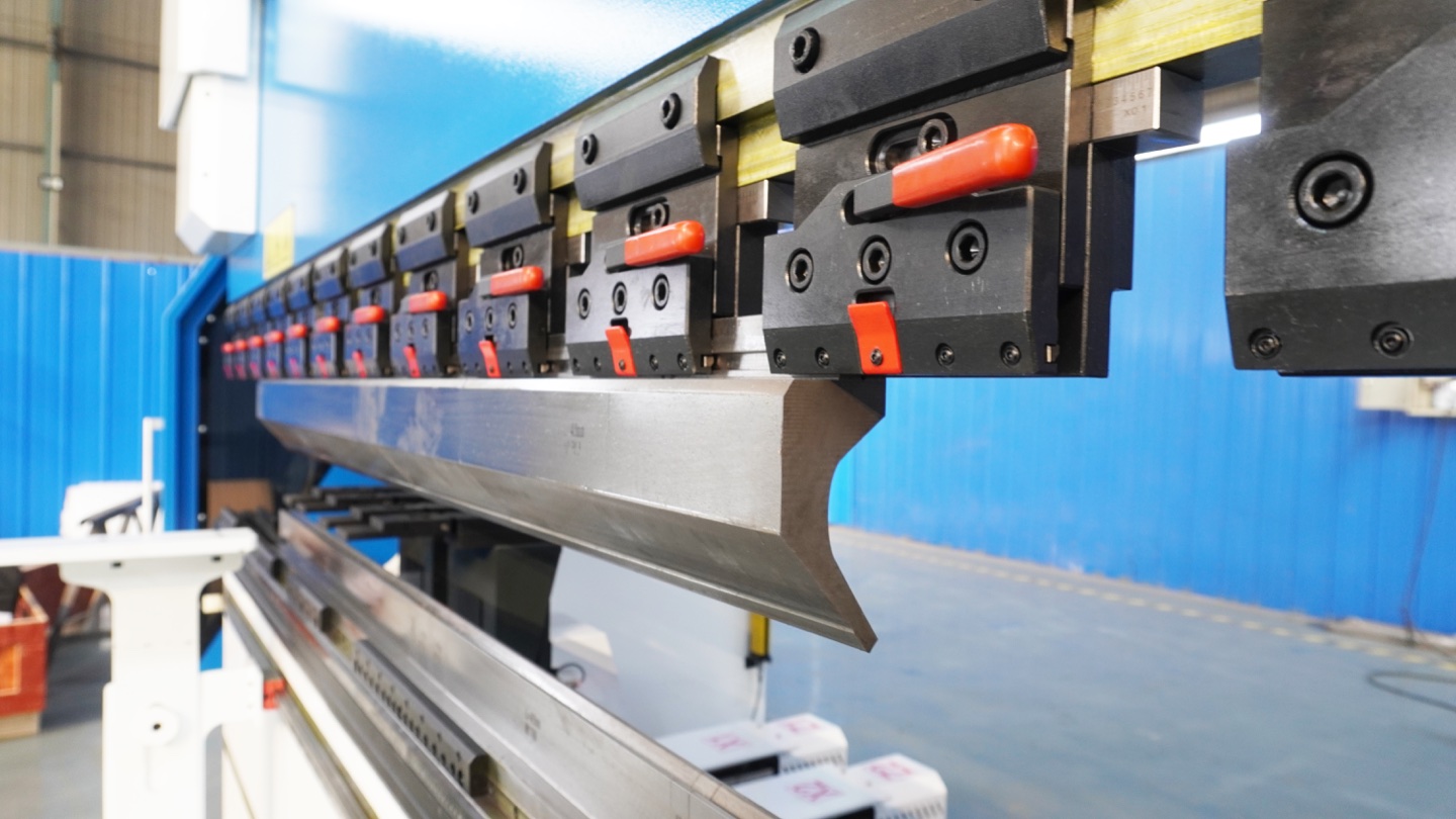
Segmented press brake tooling lets you assemble a working length from separate punch or die sections. Choose that length from the bend line and the space available through the complete bending sequence, then verify the tool family, holder and load limits. A set that adds up to the right number may still obstruct an existing flange or prevent part removal. Record the individual pieces and their order before qualifying the arrangement on a representative part.
Start with the bend line and the intermediate shape
For every operation, distinguish three dimensions: the bend line to be formed, the tool length assembled, and the space available between existing features. They are related but not interchangeable. WILA explains that bends in the same direction may allow tooling longer than the bend line, whereas other-direction bends can restrict freedom. Review each intermediate shape and the exit path. A flat blank that fits under a long punch does not demonstrate that the finished box can be removed.
Technical reference: WILA.
Match the tool geometry before adding lengths
Keep the section number, interface, working height, punch angle and radius, or die opening together. Equal length does not mean equal profile or compatibility. Confirm that the proposed pieces belong in the approved assembly, including adapters and holders. Use the actual supplier drawing and machine documentation; a familiar brand name or similar-looking tang is insufficient. Review upper and lower arrangements separately.
Two ways to assemble 300 mm
The following is an inventory-planning example, not a standard tooling set or a recommended machine setup. Assume both alternatives are available in a matched, suitable profile. Each reaches 300 mm, but the number of pieces and joint positions differ. All lengths are nominal millimeters; actual geometry and application still require verification.
| Illustrative layout | Nominal lengths, left to right | Total | Joint positions from the left end |
|---|---|---|---|
| A: five pieces | 100 + 100 + 50 + 30 + 20 mm | 300 mm | 100, 200, 250 and 280 mm |
| B: two pieces | 200 + 100 mm | 300 mm | 200 mm |
These positions are a record for review, not a rule that a joint is always allowed or forbidden at a given feature. Layout B has fewer joints; layout A uses smaller pieces that may also serve other jobs. Neither is automatically faster, safer or more accurate. If the required arrangement is 315 mm, rearranging the same 300 mm of inventory cannot supply the missing 15 mm. Request a compatible alternative rather than creating an unsupported gap under the bend.
Check horn orientation and box removal
WILA describes horn sections with cutouts that accommodate reverse flanges. Specify the actual left/right geometry and its position in the assembly; do not treat every end segment as a horn. Check the forming path, previously bent walls and the route for removing the part. WILA also notes that horn deflection can affect corner angles. Inspect the relevant corner results against the drawing instead of assuming the center measurement represents the whole part.
Technical reference: WILA.
Technical reference: WILA.
Available length is not available capacity
Do not infer the load capacity from the total length of tooling installed on the bed. Record the length actually loaded and the intended process, then check the punch, die, holders and machine under their documented loading conditions. WILA's load guidance explicitly distinguishes evenly distributed loading and identifies holders or the machine as possible limits. The arithmetic in the layout example proves only length sums; it does not qualify concentrated, uneven or off-center loading.
Technical reference: WILA.
A reusable segment-selection record
Create one line per operation and retain the evidence below with the program revision. A purchasing list and a validated production arrangement serve different purposes.
| Record group | Keep with the job |
|---|---|
| Part and operation | Drawing revision, bend line, intermediate shape, required angle and the features restricting access. |
| Physical tooling | Actual part numbers, lengths and quantities; order from a stated datum; horn orientation; upper and lower layouts. |
| Assembly conditions | Matched profiles, heights, holders and adapters; load documentation; insertion, forming and removal checks. |
| Inspection and reuse | First-piece angle and flange results, corner and surface checks, measurement locations, program revision and changes requiring another trial. |
Qualify the arrangement before repeat production
- Group the recurring parts by actual bend-line and clearance requirements. List the available segments and quantities; do not assume a catalogue set includes every length shown in a supplier's examples.
- Have the proposed tool and holder assembly checked for the machine, material and forming process. Use simulation where applicable, with accurate tool geometry and intermediate part shapes.
- Follow the machine and tooling instructions for handling, installation and the controlled trial. Do not reposition a segment under load, defeat guarding or improvise a retaining or load-bearing arrangement.
- Inspect a representative finished part at the agreed locations, including corners near horn sections and surface-sensitive areas. Save the accepted arrangement with tool identifiers. Recheck relevant conditions after changes to stock, tooling, program or setup.
Segmented-tooling questions
Is a segmented punch the same as staged bending?
No. Segmentation divides a tool length into pieces. Staged bending places multiple tool combinations along the machine for different operations. A station may use segmented tooling, but its common shut height, clearances and sequence still need a separate review.
Does a gap-free joint guarantee an unmarked part?
No. A visually closed joint is not proof of matching working heights, tool condition or an acceptable surface result. Verify the actual assembly and inspect the specified finish on a representative part. Do not promise mark-free output from the word segmented.
Can I combine spare segments from different sets?
Only after the supplier or responsible setup review confirms the actual interfaces, profiles, heights, retention and load conditions. Similar nominal lengths do not establish compatibility. Record replacement pieces and repeat the affected checks before treating the arrangement as approved.