
Staged bending places several tool combinations along a press brake so a part can move between operations without a tool change between those operations. The combinations need a supplier-confirmed compatible shut height, sufficient working space and a checked program for the complete setup. Matching tool height alone does not establish collision clearance, allowable load or finished-part quality. Plan each station and every transfer before comparing the route with separate batch setups.
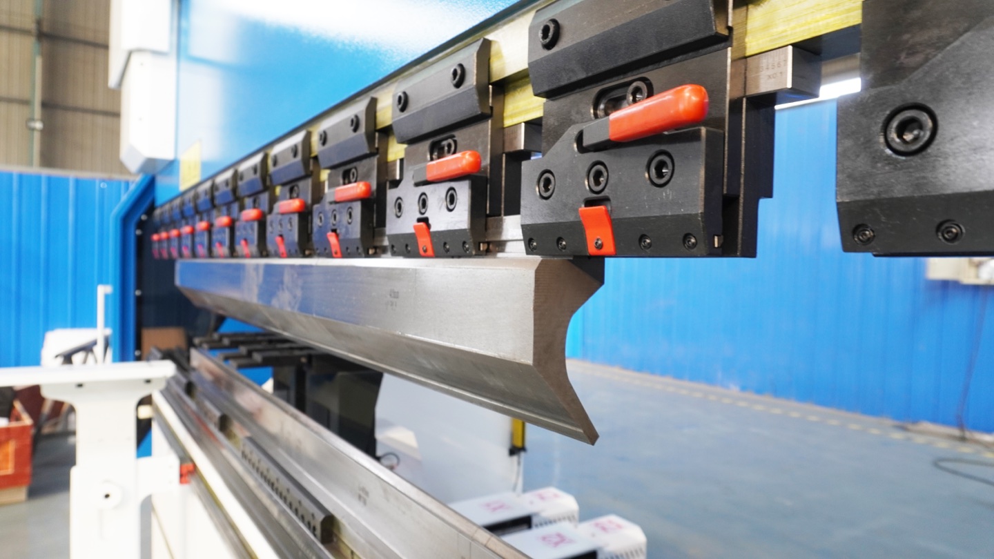
What changes when tooling is staged?
With separate setups, a batch may complete one operation before the tools are changed for the next. With staged tooling, the required combinations occupy different positions on the bed during the same setup. The operator follows the approved sequence between stations. This is sequential processing of a part; it does not automatically mean that several parts or stations are loaded in the same stroke.
Compare the production routes
| Job situation | Route to evaluate | Evidence needed before choosing |
|---|---|---|
| A repeat part needs different tool profiles | Staged setup versus separate batches | Compatible assemblies, station positions, complete sequence and measured transfer time |
| One tool combination completes the job | A single setup may already serve the part | Actual setup, handling and inspection time; an extra station needs a specific purpose |
| Long or heavy parts must move between stations | Review handling before adopting staging | Supported transfer path, available bed length, machine loading limits and operator access |
Common shut height is an assembly condition
Wilson Tool describes staged combinations as closing at a common height and warns that incompatible heights can cause tool collision. Identify the manufacturer's reference surfaces and the exact punch, die, holder and adapter combination. Equal punch height, a similar catalogue name or a matching V opening is not enough to approve a mixed set.
Manufacturer reference: Wilson Tool.
A shared shut-height system does not make every operation use identical ram penetration. Different angles, materials and forming methods still need their own approved settings. Review all installed stations at every programmed ram position, including stations with no workpiece. Obtain confirmation for any height adjustment or extension; do not improvise a shim stack to make an unverified combination fit.
Create one record for each station
Use the following fields alongside the drawing and tool layout. Give every station a stable ID so the program, setup sheet and inspection results refer to the same physical position. Missing information remains an open item, rather than being replaced by a nominal machine capacity.
| Record field | What to capture | What it prevents |
|---|---|---|
| Position and occupied length | Station ID; tool start/end positions from the machine datum; segment arrangement; adjacent stations | Confusing total bed length with usable working and transfer space |
| Complete tool assembly | Punch, die, clamp/holder and adapter IDs; height references; approved combination and load limits | Assuming that a common height also proves interface compatibility or capacity |
| Operation and loading | Bend ID; material and thickness; method; contact length; required force; station-specific machine limits | Assigning the entire machine tonnage or unused tool length to a short active bend |
| Motion and acceptance | Gauge contact; formed-part orientation; neighbouring-tool clearance; transfer and removal path; drawing checks | Approving isolated bends while overlooking a collision or an unmeasurable finished feature |
Example: a bracket with a return flange
Consider an illustrative bracket that requires one tool profile for its first bends and a relieved profile for a return flange. Label the proposed stations A and B and attach the intermediate part shapes to the bend list. At B, the already formed leg may enter the space beside A even though it clears B's punch. Model that neighbouring assembly too. If the transfer or final removal fails, revise the layout or sequence and repeat the review. This example specifies no universal station spacing or approved tooling dimensions.
Review the complete setup before production
- Freeze the drawing, material condition, tool list and machine configuration. Confirm the tool interfaces and height references with the supplier. Bystronic's tooling guidance distinguishes segmented lengths and common-height tooling; neither feature alone establishes that an arbitrary combination is suitable for staging.
- Review required force against the applicable punch, die, holder and machine limits at each active station. Keep the actual contact length and loading arrangement with the result. WILA's load guidance requires the complete load path to be considered. A vacant neighbouring station provides no additional capacity for the bend being made.
- Check approach, bending, ram return, gauging, transfer and removal with the complete installed layout. Include formed walls, clamps, adjacent tools and supports. Follow the machine maker's procedures for setup verification and safeguarding; a simulation screenshot does not authorize a physical trial with unresolved interference.
- Verify a complete representative part, not only an individual bend from each station. Record angles, dimensions, surface condition and the drawing's acceptance criteria. Save the approved station layout and program revision together. Reassess affected checks after moving a station, replacing a tool or changing material.
Compare time with a measured route, not a promised percentage
For a planning estimate, use total time = setup time + quantity × complete-part time. Include handling and inspection consistently in both routes, and use the same batch size. Staging can require more initial preparation, so a shorter part cycle does not automatically save time on a small order.
T = S + Q × t; break-even Q = (S_staged − S_batch) / (t_batch − t_staged)
Hypothetical example: separate batch setups total 12 minutes with 100 seconds per completed part; the staged route needs 18 minutes and 75 seconds per part. The additional setup is 360 seconds and the saving is 25 seconds per part. Equality occurs at 14.4 parts; at 15 parts the staged route totals 2,205 seconds versus 2,220 seconds. This 15-second difference is only arithmetic, not measured Rucheng productivity. If the staged cycle is no shorter, this break-even calculation does not establish a saving. Include tooling cost, rejects and handling constraints in the wider decision.
Staged-tooling questions
Do all stations bend at the same time?
No. This guide describes moving a part between sequential operations. Simultaneous loading is a different arrangement that needs its own machine, tooling, force-distribution and safeguarding review; do not infer permission from the word staged.
Can existing tools be combined if their heights match?
Height is only one check. Confirm the complete assemblies, interfaces, tool angles, closure behaviour, load limits and clearance over the whole program. Ask the tooling supplier to identify which combinations are approved together.
Does a successful simulation prove the production result?
Simulation depends on accurate models and settings. It supports the motion review, but does not replace approved setup checks or representative-part inspection. Record any unmodelled holders, supports or handling movements as unresolved items.
Prepare the supplier discussion
For a Rucheng Machinery review, provide the part drawing, bend list, material range, quantity, available machine information and existing tool IDs. Ask for an itemized station layout, compatibility and load review, transfer assumptions and a representative trial scope. Confirm supplied tooling and options separately; a general CNC machine description does not guarantee staged-tooling capability for your part.
Discuss the machine and tooling requirements