
An offset or joggle in sheet metal uses opposing bends to create a step between two areas of the part. A press brake may produce that geometry with separate bends or a matched offset tool, depending on spacing, radius, material and access. Define the finished step and its reference surfaces first. A tool's nominal Z dimension is not a complete part specification, and a single-bend tonnage estimate is not an offset-tool load approval.
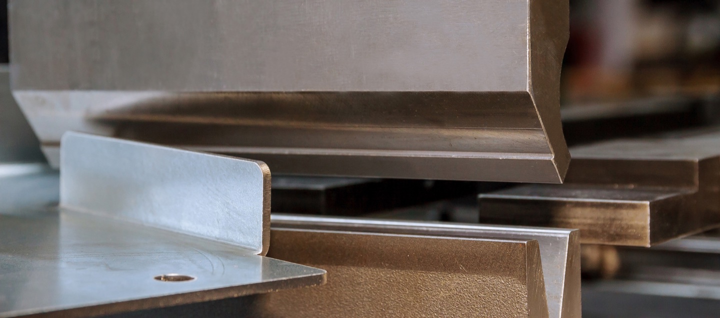
Define the finished offset before selecting a tool
On a section drawing, identify both bends, their directions, inside radii and angles, the connecting web and the two surfaces used to measure the step. State whether the height is measured between corresponding faces, opposite faces or theoretical lines. These dimensions are not interchangeable when sheet thickness is included. Keep bend-line spacing separate from finished offset height.
Separate bends or matched offset tooling?
WILA describes dedicated offset tooling that forms two opposing bends in one stroke. Mate also lists paired Z-offset inserts and holders. These are specific tooling systems, not proof that any punch with an offset body produces a joggle. The following comparison is a planning aid; the selected route still needs supplier review.
Manufacturer references: WILA; Mate.
| Proposed route | Check before selection | Record for production |
|---|---|---|
| Two separate bends | Can the first flange clear the die and punch during the second bend? Can each stage rest on the intended support and reach its gauge datum? | Bend order, tool geometry, orientation and datum for each operation; inspect after the second bend. |
| Matched offset punch and die | Does the approved tool pair suit the specified material, step, angles and radii? Check contact throughout forming and the complete assembly's permitted loads. | Matched part numbers, holders, approved process, setup revision and finished-step acceptance criteria. |
| Special tooling or drawing revision | Use a supplier-reviewed alternative when neither route provides the required geometry, support or clearance. Obtain the designer's approval for part changes. | Approved drawing change or special-tool proposal, trial scope and acceptance record; do not release from a sketch alone. |
Check flange contact throughout the forming path
A section that fits at the end of the stroke may still be poorly supported earlier. Eurostamp's offset-bending guidance shows why flange contact during forming matters, rather than checking only the final position. Ask the tooling supplier to review the actual flange lengths, entry and exit path, holders and nearby features. Review handling and safeguarding under the machine manufacturer's procedures; a drawing comparison is not an operating instruction.
Manufacturer references: Eurostamp.
Keep force and tooling ratings separate
Mate warns that offset forming can require more than twice the force of a single bend. Do not turn that warning into a universal multiplier. Obtain a process-specific force assessment for the material, thickness, formed length and selected tools. Check the punch, die, inserts, holders, adapters and machine limits together, including any side-thrust restrictions. A larger press brake rating does not increase an individual tool's allowable load.
Manufacturer references: Mate.
A drawing and setup record for offset work
| Record item | Information to agree |
|---|---|
| Part and material | Drawing/flat-pattern revision, grade and temper, thickness, rolling direction where relevant, bend length and surface requirements. |
| Finished geometry | Named step-height reference faces, both angles and radii, connecting-web dimensions, nearby holes, mating-part fit and drawing tolerances. |
| Machine and tooling | Machine identification, exact tool/holder combination, approved load conditions, opening and stroke clearance, support and gauge plan. |
| Inspection and release | Measurement method and locations, representative trial material, recorded results, approval owner and changes requiring another first-piece check. |
Example: an overlapping enclosure cover
Consider an illustrative 1.5 mm cover intended to overlap another panel with a flush outer face. Specifying only a 1.5 mm joggle leaves questions about the measurement faces, coating or seal, bend angles and mating fit. Do not assume two 90-degree bends are feasible at that shallow step. Have the designer and tooling supplier review the transition geometry, then inspect the representative assembly. This is a drawing-review example, not a tested Rucheng part or a tooling recommendation.
Inspect the result before approving repeat work
- Confirm the approved drawing, material and tool combination. Keep changes to a flange, radius, relief or process traceable to a revision.
- Review each intermediate shape, gauge contact, tool clearance and removal path. For a matched tool, review the forming path as well as the final shape.
- Measure the released part against the agreed datums: step height, both angles, radii where specified, parallelism and nearby feature positions. Use drawing-defined locations and tolerances; no generic allowance replaces them.
- Check the mating assembly and surface condition. Record results and approved corrections. A change of material, tool combination or bend order may require another representative first piece before batch release.
Request a proposal against the complete part
For a Rucheng Machinery press brake inquiry, send the formed drawing and flat pattern, material, thickness, bend lengths and batch requirements. Identify the offset and its critical fit. Ask for an itemized machine and tooling proposal, with feasibility, trial requirements and supplied scope confirmed separately.
Send press brake requirementsOffset bending questions
Is a joggle punch the same as a gooseneck punch?
No. A gooseneck body provides clearance for an existing flange. A matched offset tool forms an opposing bend pair. Confirm the actual tool drawing and intended process instead of relying on the name.
Can I calculate an offset by doubling single-bend tonnage?
Do not use that as an approval rule. The selected geometry and forming process determine the required force. Obtain the supplier's assessment and check every component's load conditions and the machine limits.
Does one stroke guarantee the finished step height?
No. The selected tool, material and forming process must be checked against the drawing. Verify the released part and mating fit in a representative trial, then retain the accepted setup and inspection record.